Custom Printed Circuit Boards
Altium Designer
Laptop Battery Case PCB
I designed this PCB in Altium Designer for my laptop battery case invention. The PCB has a battery management system, state of charge meter, dynamic power delivery and a USB C interface. The short video on the left shows a development PCB I designed with the state of charge meter properly displaying the charge level of the battery pack. I also programed and validated the BMS system on a battery pack which I custom made using a spot welder. Once I validate the functionality of all the circuits, I will design a multilayer PCB for use in the production unit.

Dartmouth Formula Racing PCBs
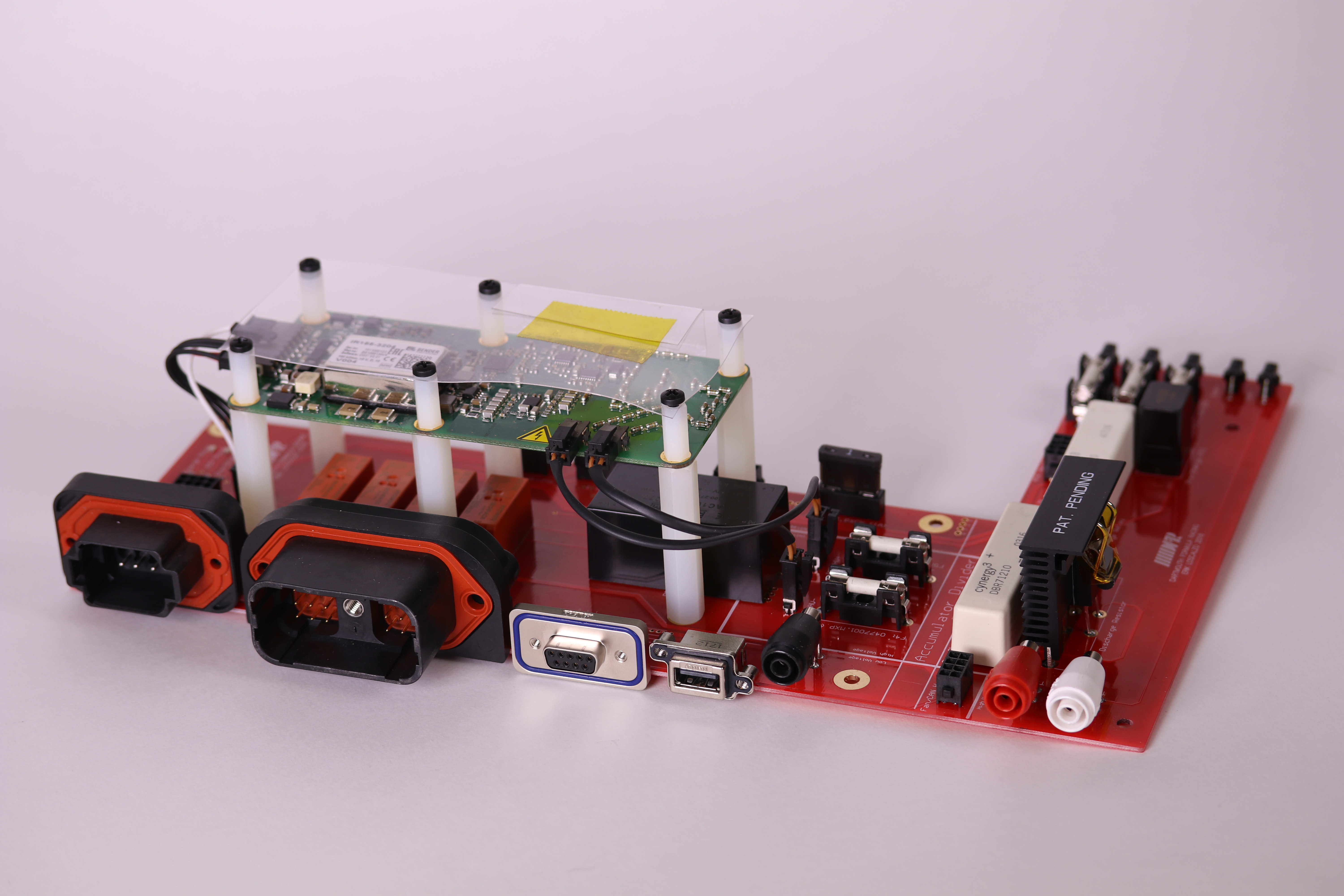
The image on the top right shows the PCB I designed for the new electric energy system on the Dartmouth Formula Racing Car. The car has a 100 kW electric motor and a 2 kWh 300V battery pack. I developed the schematic for this board to include all the necessary electronics for the high voltage system. This was my first time designing a high voltage board so I spent time making sure I properly set up Net Classes in Altium. This allowed me to program trace routing rules to make sure that I designed the board with the proper clearance to avoid arcing.
I designed the PCB to eliminate wires within the accumulator and provide a reliable, clean interface for both internal and external electrical components. As space within the accumulator is tight, the board needed to densely mount all the necessary electronics. Within the enclosure, the PCB interfaces with the battery management system, isolation monitoring device, current sensor, motor controller, accumulator isolation relays, CAN network and cooling fans. The internal circuits on the PCB include high voltage (HV) precharge and discharge circuits, an HV DC-DC converter, relay safety circuitry and LED indicators. The precharge circuit charges the capacitors in the motor controller safely. The discharge circuit dissipates the electric energy stored in the capacitors when the car shuts off. Although these circuits are relatively simple, the implementation was challenging due to the high voltage and large amount of power dissipation. To verify that the circuits met the specified time constants, I developed a MATLAB circuit simulation. The layout of the 300V section of the board required extra consideration because of possible arcing. The PCB also includes connectors to external components which include the car’s LV system, programing ports for the motor controller and BMS, charger and HV tractive system measuring points.